|
|
Power Spring Basics: A Power Spring in it's
simplest form is a flat strip of spring material that is cut to length, wound around a forming arbor, and unwound into
a housing. There are many names for power springs. They are commonly referred
to as coil springs, hair springs, spiral springs, clock springs, motor springs, mainsprings, recoil springs, wind springs,
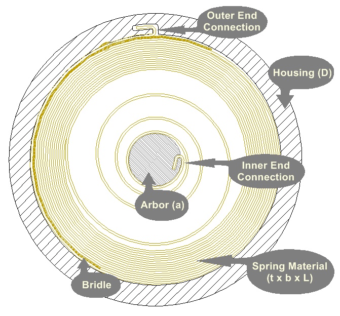
retractor springs, and flat springs. The performance of the spring is defined by the dimensions
of the spring material (Thickness (t), Width (b), & Length (L)) and the space available (Housing (D) & Arbor
(a) Diameters). Unfortunately, even though these parameters are basic, the design and performance of a power spring
is a complicated matter and completely understood by very few people in the industry. Mecca
C&S Power Spring Design Software makes the complicated design process possible using formulas and finite element
analysis. By inputting the basic parameters and adjusting the manufacturing details, an engineer can determine possible
spring performance and save significant time in the development process. This summary is
intended to provide an overview of the basics of power springs while touching on some of the more complicated factors.
|
|
Prestressed vs. Conventional: One of the most invisible differences in a power spring relates to the free
state or shape of the spring when it is not retained in its housing. A conventional spring has a shape which spirals away from center in the same
direction as it is wound. A prestressed or
backwound spring has a portion of it's shape that spirals in the reverse direction of winding. When viewed in the housing, it is difficult to determine the spring type, and both types can appear the same. The
prestressed spring, however, creates higher stresses which result in significantly higher torque. Both methods
have their advantages and disadvantages, and the best option varies depending on the application and requirements.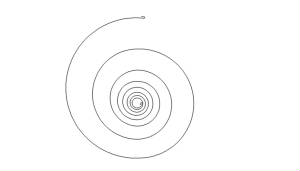 These are some advantages and disadvantages:
Conventional:
Advantages - Lower stress, Best cycle life, Easiest to manufacture.
Disadvantages - Lower torque, Lower turns, Torque not as flat
 Prestressed: Prestressed:
Advantages - Higher torque, Flatter Torque
Disadvantages
- Lower cycle life, More difficult and sometimes costly to manufacture, Size and Forming methods sometimes limited.
A
conventional spring is typically wound from a flat condition which makes it easiest to manufacture. A prestressed spring
first requires coiling (forming the material into a coil or spool) either before, during, or after cutting. Most often
it is then stress relieved (through heat treatment), and finally backwound into the housing. Our Power Spring Design Software can model both conventional and prestressed springs accurately by calculating the
free states for each design and using that information to determine spring performance. |
|
|
|
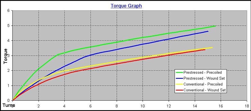
Conventional - Wound Set
|
Conventional - Precoiled
|
Prestressed - Wound Set
|
Prestressed - Precoiled
|
|
|
|
|
|
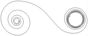
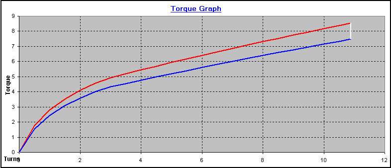
The above torque graph and spring simulations show a comparison of similar sized power springs manufactured using different methods. The higher stresses created using the prestressed fabrication methods result in higher torque output than the conventional
methods. Precoiling (see summary below) can also result in increased torque
output and can be identified by the reduction in "dead turns" or those turns visible when unwound in the housing. Also of note are the slight turn differences from both prestressing and precoiling methods.
|
Torque and Turns: Torque and turns are the most important outputs in a power spring design.
Torque commonly starts at zero, increases rapidly during the initial turns, and continues to increases at a lower rate till
it is fully wound. The resulting flattened torque curve (see torque graph below) is useful in many
applications. The torque graph shows a red and blue line. The red line
is the winding torque while the blue line is the unwinding torque. The unwinding torque or output torque is always lower
than the winding torque due to friction or histeresis. Although some is unavoidable, friction can be reduced through
proper design, lubrication, and special techniques.
Design Guidelines: 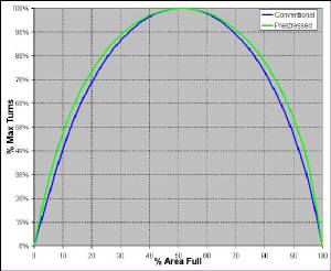 The geometry of the spring design largely determines
design turns. There is a certain amount of available space between the housing and the arbor. The % of that area
taken up by the spring material determines what % of the maximum turns available can be achieved (see % full graph).
As you can see the parabolic shape of the graph shows that as the % full is increased (by adding material length) from 0%,
turns increase rapidly. As the % full approaches 50%, however, turns do not increase significantly. Commonly,
as material is added from 45 to 50%, the increase in turns is not significant and can result in wasted material and an inefficient
design. It can also be seen that increasing the % full greater than 50% results in a decrease in turns that can be an
even more significant waste of material (note... certain applications that require cycle life sometimes benefit from
higher fill rates).
Other parameters that are important to an efficient design are the ratio
of arbor diameter to material thickness (a/t) and the ratio of length to material thickness (L/t).
Calculation of spring turns and torque is a complicated matter. Mecca C&S Power Spring Design
Software not only calculates these outputs for you, but it allows you to adjust and fine tune the design so that you can make
the spring efficient. By using the optimum thickness or eliminating unnecessary material, you can provide savings
for the life of your products.
|
|
Cycle Life: A power spring is commonly wound and unwound between two specific points or number
of turns. (For example, in a hose reel application, the spring is preloaded to maybe 3 turns. The hose when extended
winds the spring an additional 10 working turns. Therefore, the spring is wound from 3 turns to 13 turns when the hose
is extended and from 13 turns back to 3 turns when the hose is retracted. This is considered 1 cycle.) Many factors affect cycle life including stress amplitude, alternating stress,
coil friction, spring forming methods, material type, edge condition, lubrication, and special design configurations.
Because there are so many factors, cycle life is difficult to calculate. Most commonly, stresses are calculated
and an S-N logarithmic endurance curve is used to calculate the cycle life for a given material. Because there
are so many factors, once design cycle life is calculated, it is typically compared to a prototype or similar spring.
Then, by adjusting the design, the cycle life can be re-calculated to try to reach an accurate approximation for a new
design.  Any amount of cycle life testing will add development time. Having software that can estimate cycle life can
save time and money. Our design software calculates cycle life based on the calculated stresses and adjusts automatically
with changes to the design. Although no cycle life calculation is perfect, the software can steer you in the right direction
initially, and once you have a tested prototype, you can further use the software to refine the design and evaluate the changes
to cycle performance. By using these methods you can reduce your development time significantly. Any amount of cycle life testing will add development time. Having software that can estimate cycle life can
save time and money. Our design software calculates cycle life based on the calculated stresses and adjusts automatically
with changes to the design. Although no cycle life calculation is perfect, the software can steer you in the right direction
initially, and once you have a tested prototype, you can further use the software to refine the design and evaluate the changes
to cycle performance. By using these methods you can reduce your development time significantly.
|
|
Manufacturing Methods: Power spring manufacturing methods are somewhat simple, although the equipment
can be highly specialized. In it's most basic form, a power spring is cut to length, wrapped around a forming arbor,
and then unwrapped into a housing. For a prestressed spring, the material has to be coiled or spooled first and then
wrapped in the reverse direction around the arbor.  Many of the details including; end forms and shapes, coiling equipment, cutting dies, heating equipment, winding equipment,
and special forming methods are very complicated. Many of the details including; end forms and shapes, coiling equipment, cutting dies, heating equipment, winding equipment,
and special forming methods are very complicated.
Mecca
C&S Power Spring Design Software gives the designer control of the design output by adjusing the manufacturing details. Arbor
size, anneal length, free coil diameter, and precoiling details are both estimated and available for entry allowing designers
to fine tune the design and prepare for production at the same time.
The following discusses some of the special methods used in power spring designs. Precoiling: This is a method used to preserve the
original shape of the material and increase torque and turns. It is most often visible by a reduction in "dead
turns" observed when the spring is unwound (see comparison pictures above). When the material is wrapped around
a forming arbor the first time, the high stresses typically exceed the material yield stress which results in a permanent
shape deformation and the common spiral shape. Precoiling uses methods to reduce the forming stress and change the spiral
shape to a larger spiral. This can be done using a shim during winding, or by using multiple winding arbors, or by some
combination of both. Although precoiling tends to improve torque and also slightly increases total turns it is not without
it's disadvantages. It usually involves extra production steps, and can cause stress concentrations which can significantly
reduce cycle life. Special process forming methods can help reduce stress concentrations. Annealing: When spring material is formed to a small
radius the yield stress of the material can be signifcantly exceeded. The high surface stresses created can
sometimes cause the material to fracture or crack. In these cases, it is advisable to soften the material through
an annealing process. By heating the material till it is glowing red and then allowing it to cool, the material structure
is transformed, and the hardness is significantly reduced. Once annealed, the material can be formed to a smaller
radius without cracking. Annealing a longer length at
the inner end of the material can also change the forming radius. This is sometimes helpful because it can create a
tighter wrap of annealed material around the arbor. It also increases the arbor diameter required to form the material
resulting in a precoiling effect. Winding arbor
vs. final arbor: The final arbor or customer arbor is the arbor used to wind the spring in the end application.
The winding arbor is usually smaller than the final arbor in order to form the material to the proper inside diameter.
If the winding arbor is larger than the final arbor (as is sometimes used in special situations), the spring can never
be wound completely to solid, or it will change the free shape of the material resulting in a loss of turns, a torque
output reduction, and reduced cycle life. Winding arbors are a very important part of the manufacturing process
and have to be designed properly to form material correctly and to avoid stress concentrations. End Configurations: There are numerous ways to connect
the spring material to the arbor and housing. Material can be formed to a sharp angle to form a connection hook
or bend, it can be pierced or notched to allow a connection point, and it can even be spot welded. The design
challenge is to create a connection that is most importantly secure and secondly manufacturable at a reasonable cost. Retaining Methods: A power spring must be contained
by some method. Some commonly used retaining options are; a metal or plastic housing, a band or ring, a "C"
shaped keeper, and a riveted outer wrap of material (called an integral band). Special
Features: Sometimes, a leaf spring is added to the outer end of the spring to increase the torque and assist
in unwinding the spring to the outside of the housing. This leaf spring is sometimes called a bridle and can be very
helpful to the performance of the spring. When properly designed, it can increase torque, reduce histeresis, and improve
cycle life. These same benefits can also be achieved through a properly designed outer end connection.
|
|